[Abstract] The steel structure shelter of the main stadium of Hangzhou Olympic Sports Expo Center is composed of a space tube truss and a chord branch reticulated shell. It has unique features, a variety of structural forms, and a large cantilever span. The three kinds of structural lifting schemes were compared and analyzed by the finite element analysis software ANSYS. The influence of different assembly sequences on the deformation and stress conditions of the structure under consideration of the path effects was studied. The steel structure support based on the one-time loading method and the path effect was considered. The rack unloading process was compared and analyzed. The analysis results show that the analysis method considering the path effect is very different from the structural response calculated by the one-time loading method. The former is closer to the actual state of the structure and makes the construction process safe and reliable. The calculation and analysis can ensure the installation accuracy of the space tube trusses and ensure the safety and economy of the construction process.
1. Project Overview
The main stadium of Hangzhou Olympic Sports Center is located at the south side of the junction of Qiantang River and Qijia River. The planned building area is 229 thousand square meters. It can host intercontinental, national comprehensive sports games and international track and field and football matches. It is the Olympic sports body of Hangzhou Olympic Games Expo. The important part of the center. According to the overall project plan, the Hangzhou Olympic Sports Center Stadium will be put into use in 2015 and will become a new landmark of Hangzhou with Expo City. The "organic" design of the Olympic Sports Center is inspired by the flowers of nature. The main stadium is like a white lotus blooming on the edge of the Qiantang River (see Figure 1a).
There are 80,011 fixed seats in the main stadium of the Hangzhou Olympic Sports Center, which is a super large-scale sports building. The entire structure consists of a concrete stand and a steel structure shelter. The entire steel structure shelter consisted of 14 groups (28 pieces) of main petals and 13 petals (Fig. 1b). The outer edge of the shelter is 333m in the long axis direction, 285m in the minor axis direction, the maximum width of the shelter is 68m, the cantilever length is 52.5m, and the highest point elevation of the shelter is 59.40m.
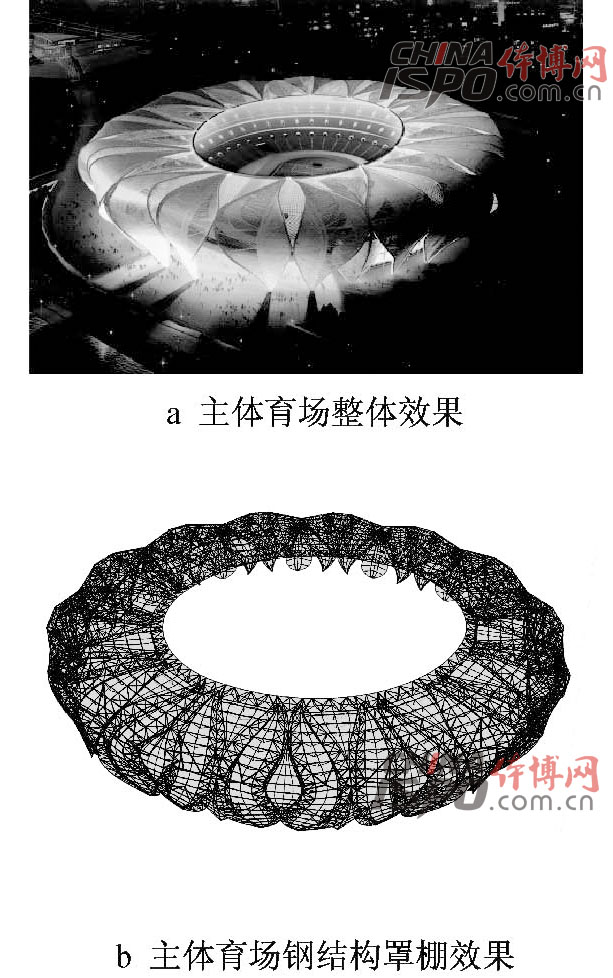
Figure 1 Overall effect of the main stadium and steel structure shelter effect
Fig. 1 Rendering of the whole structure of the main stadium and rendering of its steelâƒstructure awning
2. Steel structure shelter structure system
The steel structure shelter of the main stadium of Hangzhou Olympic Sports Expo Center is a spatial pipe truss + chord branch single-layer reticulated shell steel structure system (see Figure 2). The main petal is a tube truss structure. The main petal and the main petal and the main truss is a chord-supporting single-layer reticulated shell structure. The entire steel structure canopy is supported on the concrete stand and platform by the upper, middle and lower supports. The steel roof is divided into three parts: wall surface, shoulder, and cantilever. The cast steel joints are used at structural supports, main truss joints, truss and support column joints, primary and secondary petal joints, etc. The in-ground cantilever ends are connected to the ring truss using direct joints. The main rod steel section of the roof is made of round steel pipe. The seamless steel pipe and welded straight seam steel pipe are used for the round steel pipe. The Q345C is used for all main truss members, the Q345B is the secondary member, and the φ700 × 35 is the largest diameter member.
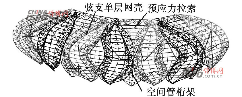
Figure 2 Steel Structure Shed
Fig. 2 Steel structure awning
3, the construction process simulation analysis
3.1 Construction Simulation Analysis Method
The main difference between the construction process simulation analysis and design status analysis is whether or not the path effect problem is considered. The construction simulation method adopted in this paper is a one-time modeling method based on the ANSYS life and death unit technology. This method is more than a step-by-step modeling method. The advantage is that the geometric nonlinearity can be considered and the analysis accuracy is high; the step-by-step modeling method can only analyze the stress state of the existing model, and cannot consider the influence of the previous installation configuration on the subsequent construction steps, ie, the construction cannot be considered. The order of the different path problems.
3.2 Construction Simulation Finite Element Model
This project mainly adopts the space tube truss structure system. The construction of the finite element model for construction simulation analysis should be consistent with the actual project. The traditional method is to use elastic constraints to simulate the temporary support frame. This method calculates the deformation and internal force of the obtained structure. Too small, this article uses ANSYS parametric programming to establish the support frame into the model, so that it participates in force deformation; in the uninstall analysis using the "temperature control jack unit" to control the unloading stroke. The finite element model was established using ANSYS finite element software based on the actual steel model and section size used in this project. (See Figure 3)
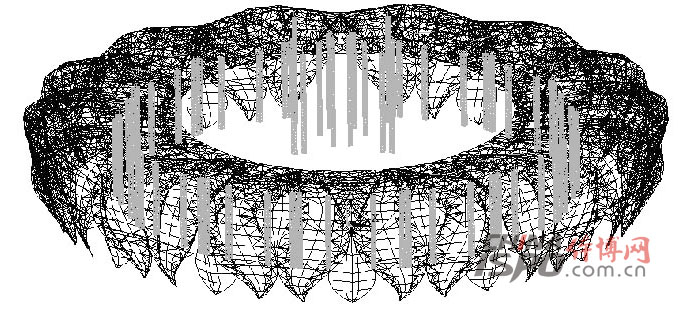
Figure 3 Construction simulation finite element model
Fig. 3 FEA model of construction simulation analysis
1) Unit type and material properties Tube truss and net shell rods were selected for beam simulation with Beam 189. The unit is a 3D linear finite strain beam element suitable for analysis of slender to medium elongated beam structures; prestressed cables and steels Bars are modeled using Link10 units. During the unloading process, the Link10 temperature controlled jack unit simulates the stroke control. Density of steel is 7 850kg / m3; Elastic modulus: 1.9 × 10¹¹N/m2 for pulling, 2.06 × 10¹¹N/ m2 for pipe truss, 0.3 for Poisson ratio, temperature control jack unit can be increased Elastic modulus to ignore the vertical deformation caused by pressure, the unit unloading stroke is controlled by setting the linear expansion coefficient α, α can be obtained by the formula: α = Δ/LT, where Δ is the unit unloading stroke and L is the unit length. T is the cooling value.
2) Boundary Conditions Since the space tube truss connection nodes are intersecting nodes, the steel structure part and the concrete stand upper, middle, and lower three-layer bearings are all welded and connected by the embedded steel bearing node, so the model node connection uses a rigid connection. The bearing is a fixed bearing.
3) Load value Construction simulation analysis considers the most unfavorable combination of construction dead load (structure weight), live load (construction live load) and temperature effect. Because a large number of cast steel joints are used in the structure and the mass is relatively large, considering the quality of cast steel joints, horse tracks, purlins, etc., the constant load partial coefficient is taken as 1.5. This paper analyzes the stress and deformation of the structure under the combined conditions of 1. 5 dead load + 0. 98 live load + 0. 7 temperature load (cooling down 25 °C).
3, steel structure construction program and lifting program
3.3.1 Structural Construction Plan
Combined with the characteristics of the project, through the comparison and analysis of various construction plans, the high-altitude block lifting method was selected for construction. The stadium steel structure shelter is an annular closed structure and is divided into four construction areas for construction. This division of construction areas can make full use of the zoning site for the trussed unit's ground assembly, and the construction of each area will not affect each other and improve the construction efficiency. The structure hoisting is divided by (1âƒ5a) axis, (1âƒ15a) axis, (1âƒ25a) axis and (1âƒ36a) axis. Construction of areas C and D was first followed by construction of areas A and B. The final structure was completed near the (1âƒ5a) axis and (1âƒ25a) axis (see Figure 4).
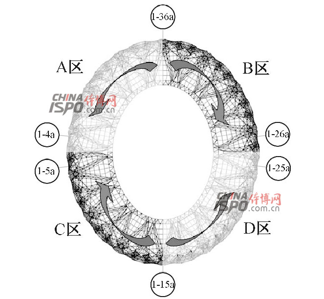
Figure 4 Construction Area Division
Fig. 4 Division of construction area
3.3.2 Tubing Truss Unit Lifting Plan
In addition to the openings in the steel structure shelters, a set of petal support rods is slightly different, and the remaining 13 groups of petal support arrangements are basically the same. After the overall construction plan was confirmed, the assembly of individual petals was analyzed. The truss was assembled on the ground and used large-scale crawler cranes inside and outside the yard to hoist. First, the main trusses of petals are divided into multiple units for lifting. When dividing, the factors such as unit stiffness, splice position, and structural stability are taken into consideration.
After the lifting unit is divided, the lifting sequence must be clearly defined and the unit must be assembled at the construction site. The unit assembly site needs to be leveled to ensure that the unit assembly and positioning are accurate. The main truss unit division and three kinds of lifting schemes are shown in Figure 5.
1 Scenario 1 Lifting with a set of lower back support from the petals, first install the outer ring truss and then install the inner ring cantilever truss, then install the ring truss, the whole process to form a set of back petals;
2 Option 2 Lifting with a set of lower petals of the opposite petals starting from the outer ring to the inner ring to form a set of opposed petals;
3 Option 3 is to install the direction of the outer ring first. After the installation of the outer ring is basically completed, the cantilever and the ring truss are installed.
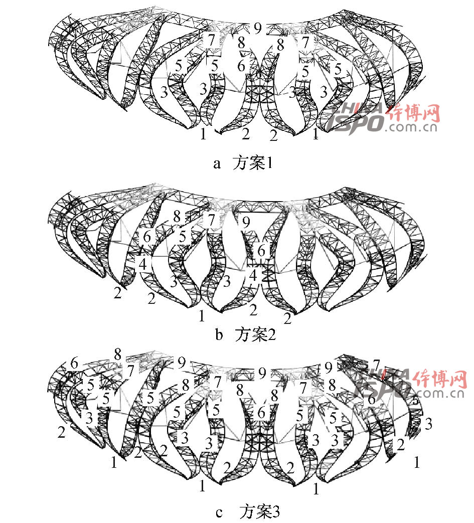
Figure 5 Division and hoisting scheme of construction simulation structural units
Fig. 5 Divide the structural element of construction simulation and lifting schemes
Figure 6 shows the maximum displacement curve and the combined maximum stress curve of the three lifting schemes at different lifting steps. Figure 7 shows the comparison curve of lifting scheme 3 and the one-time loading method. The main truss on the left side of the (1âƒ15a) axis is selected. Down to the top 20 nodes. From the comparison of the data in Figure 6, it can be seen that the rigidity of the structure during the installation of Option 2 is higher than that of Option 1, and the solution of Option 3 is basically the same as that of Option 2. During the lifting of the ring truss, the adjacent petals affect each other, so the structural stress and displacement will be Increased. Compared with Scenario 1, the advantage of Scenario 2 is that the structure is more stable, the overhanging end stiffness is larger, and the structural deformation is relatively small; the disadvantages are that the lifting steps interfere with each other and affect the lifting efficiency. Construction Plan 3 has the advantages of Option 1 and Option 2. It has the advantages of high construction efficiency, taking into account the truss production cycle, and fully utilizing the assembled tire frame. The actual construction process uses Option 3, and the entire lifting process is shown in Figure 8. . The data in Fig. 7 shows that the one-time loading is significantly different from the structural response considering the path effect. This is because the entire structure acts cooperatively during one-time loading analysis. In the actual construction process, the structure is completed step by step, and the current construction step is completed. The rear structure has been subjected to force; the z-direction displacement change in the lifting process is most distinct from the one-time loading. When the support frame is insufficient, the cantilevered end is more affected by the path effect, which requires the pre-cambering to be considered during design and construction. .
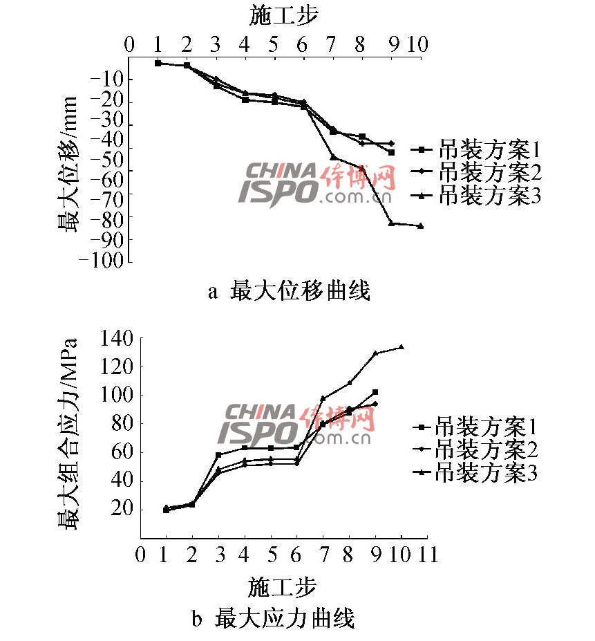
Figure 6 Maximum Displacement and Maximum Stress Curve
Fig. 6 The maximum displacements and maximum stress curves
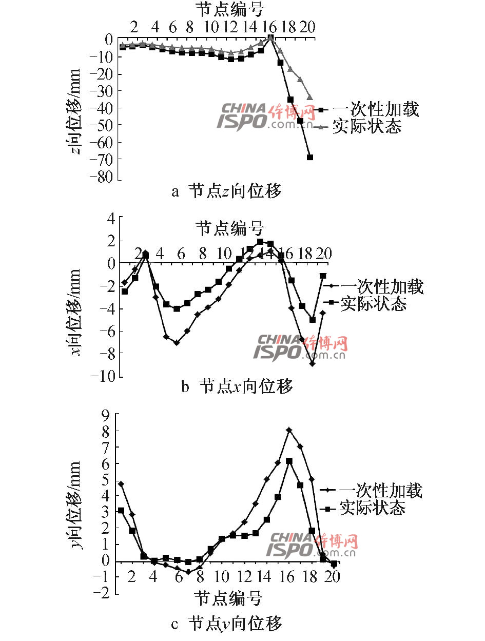
Fig. 7 Displacement of main truss nodes
Fig. 7 The displacements of main truss joint

Figure 8 main installation steps of steel structure
Fig. 8 Major installation procedures for steel structure
Loading method | Z-direction maximum displacement/mm before unloading | Top truss maximum stress / MPa before unloading | Z-direction maximum displacement/mm after unloading | Truss maximum stress/MPa after unloading |
Considering the effect of path effects | 74.6 | 145.0 | —249.3 | -200.0 |
One-time loading | 40.5 | 74.1 | -214.6 | —140.0 |
Table 1 Comparison of calculation results of one-time loading and consideration of construction route effects
3 .4 support rack unloading
According to the characteristics of the project structure, the construction and installation scheme uses 68 temporary support points, which are supported on the outer nodes of the cantilevered truss and the openings of the petal truss nodes. The unloading of the support frame is synchronous equidistant and proportional unloading. The unloading uses the jack extraction shimming method. Each support point is supported by jacks and gaskets. The gasket thickness is 5, 10, 20, 30mm. Steel plate. When unloading, according to the theoretical calculation, the gasket is extracted through the jack.
This paper adopts the calculation method based on ANSYS software's life-and-death element technology to consider the influence of the path effect, and obtains the reaction force of the temporary support and the internal force and displacement of the unloading phase structure before and after unloading.
Figure 9 compares 68 support point reaction forces under two calculation methods. The comparison shows that the installation method of considering the path effect and the one-time loading method have different reaction forces to the temporary support frame. The reaction force generated by the one-time loading of the structure as a whole is relatively small compared to the analysis result considering the path effect. In this article, the individual supporting reaction force is smaller than the reaction force generated by the one-time loading. This is in contrast to the cantilever truss unit. The installation sequence and quality are different. The one-time loading makes the cantilever part act on the force. In the actual process, the unit is already involved in the force (deformation). This will make the adjacent lightweight cantilever truss lower support frame. The reaction force decreases. When designing the temporary support, the problem of the increase in the reaction force of the support due to the path effect should be fully considered. This will help to improve the safety of the support frame during the construction process.
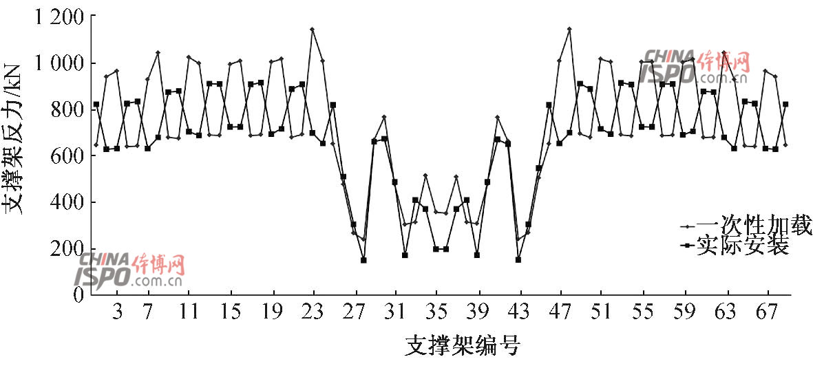
Figure 9 Support Reaction Force
Fig. 9 Reaction of temporary supports
Fig. 10 is the maximum vertical displacement curve of the structure based on the above two kinds of unloading calculations before the unloaded state. The vertical displacement values ​​of the structural ring direction nodes (A3615, B3630) and the short axis direction (C4397) are selected. Table 1 shows the displacement and internal forces of the structure before and after unloading considering the construction effect and one-time loading. From the comparison of the above data, it can be seen that the unloading method based on the path effect is obviously different from the unloading method of one-step molding. The former requires the internal force and displacement of the structure to be larger than the latter, and the simulation method considering the path effect is closer to the construction of the structure. Actual stress and deformation, and more secure and reliable.
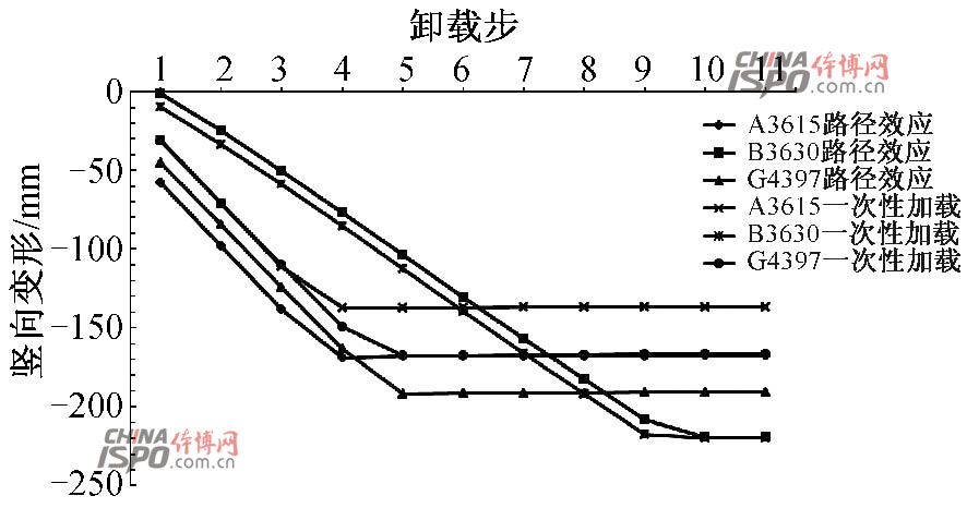
Figure 10 Vertical deformation curve of inner ring node
Fig. 10 Measured deformation curves of inner ring joint
4 Conclusion
This article analyzes the entire process of construction of the steel structure shelter construction for the main stadium of Hangzhou Olympic Sports Expo Center. It compares three kinds of lifting schemes and comprehensively considers various factors, and proposes a reasonable lifting sequence; it compares the path effects during lifting and unloading. The difference between the calculation method and the one-time loading method leads to the following conclusions.
1) Analyze and compare the construction simulation of the steel structure part of the main stadium, and finally confirm the installation plan of the multi-point synchronous hoisting of the outer ring to the inner ring. The analysis shows that the plan 2 has higher rigidity than the construction plan 1. , Option 3 At the same time with the advantages of Option 2, it also has the advantages of high utilization rate of assembled tire frame and quick construction speed. Aaa
2) Through the simulation analysis of the steel structure of the main stadium, the path effect has a great influence on the internal force and deformation of the structure; the internal forces and deformations of the structure obtained based on the road effect can provide reference for the actual construction.
3) The use of ANSYS software for life-and-death cell technology and Link10 unit features verify that the “temperature-controlled jack unit†can achieve better control of the structure's unloading stroke.
4) Through the simulation of the unloading scheme, it is concluded that the unloading method based on the path effect will obtain a more accurate counterforce of the support frame, which will help ensure the safety of the structural construction.
Diaper Caddy
Diaper Caddy,Diaper Baby Bag,Baby Diaper Bag,Waterproof Baby Diaper Bag
WENZHOU HAGO HOUSEHOLD GOODS CO., LTD. , https://www.wzhago.com
